Autonomous Tri-spoke Amusement Ride — 180:1 Spur Compound Drivetrain, Machine-Element Design & Safety-Critical Embedded Thermal Control
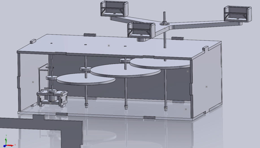
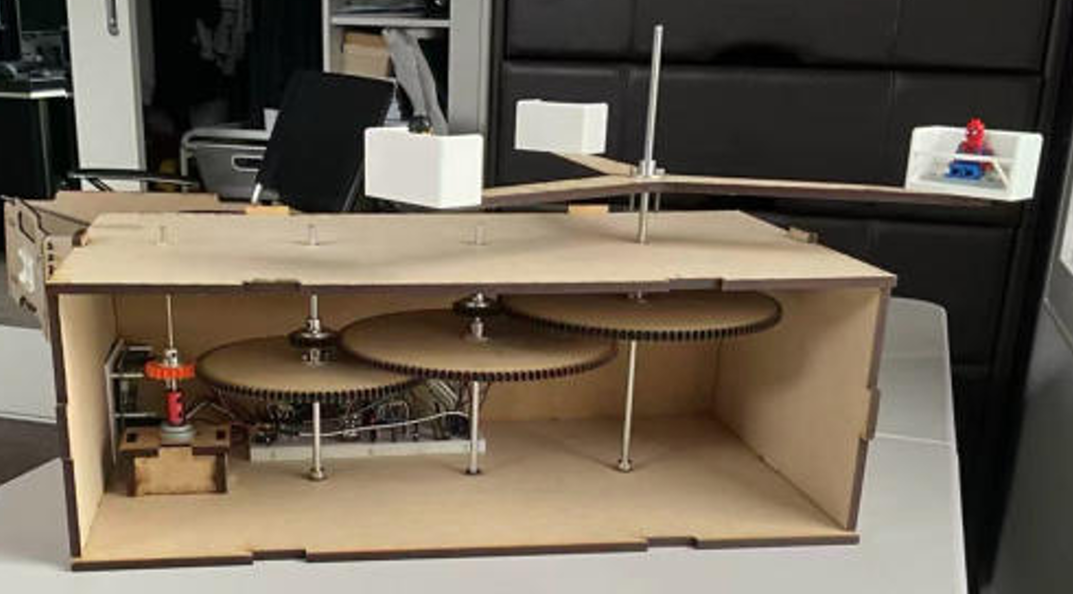
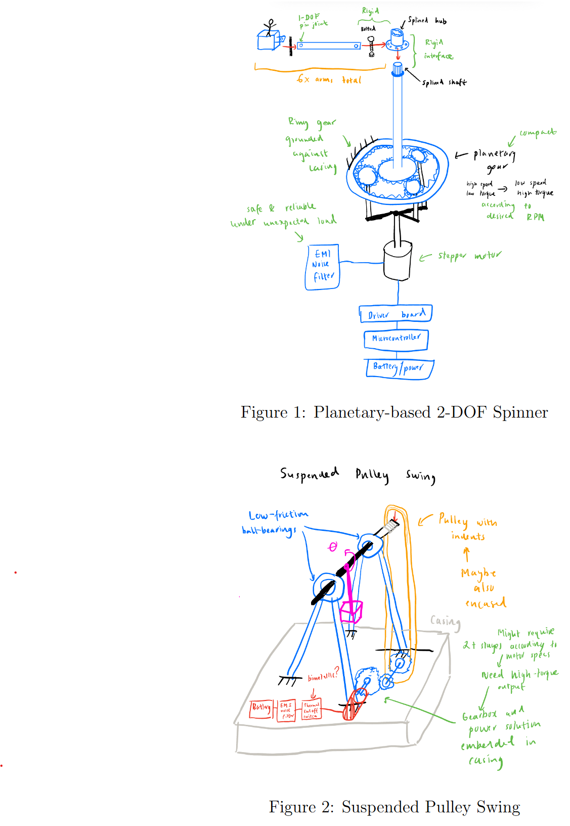
A scaled semi-autonomous amusement ride: a 6000 rpm DC motor stepped to 33.3 rpm through a three-stage compound spur reduction (5:1 × 6:1 × 6:1 = 180:1), driving three arms through a pre-programmed ride cycle with dual independent safety interlocks. Concept selected by weighted Pugh trade-study, then reversed mid-project on A/B test evidence — the prototyped stepper/planetary architecture was replaced with a DC compound drivetrain when measured motion quality, vibration, and power draw failed the design intent. Every gear mesh cleared against interference/undercut limits and Lewis bending stress; final build measured at 2.43 W steady-state against a 2.5 W budget and survived five minutes of continuous full-load operation.
- Spur-gear design from standard tooth data — module 1.5, 20° full-depth, addendum/dedendum, centre distances — with per-mesh interference/undercut checks (pinion Nmin / gear Nmax) in scripted MATLAB workflow.
- Lewis bending face-width sizing: interpolated form factors, Kv = 1.3, Kf = 1.5, 8 MPa MDF allowable at FoS 3.
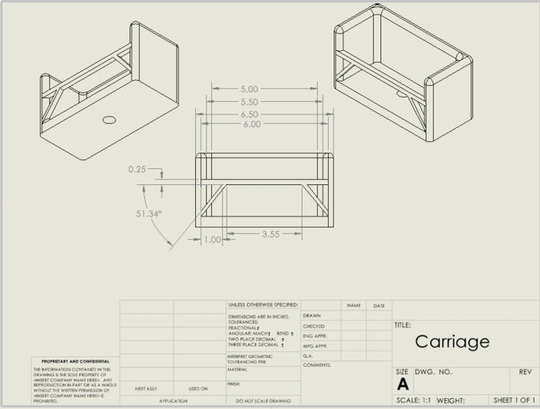
- Cantilever arm sizing from FBD and method of sections — combined distributed self-weight and point load into σ = Mc/I against UTS for timber/MDF/acrylic.
- Shaft torsion checks: τ = Tr/J (2.97 MPa against material allowables) and θ = TL/JG twist (0.19°–2.0° across aluminium, acrylic, MDF, PLA).
- DC motor modelling from datasheet primitives: linear torque–speed line, operating point, ramp sizing against rotational inertia.
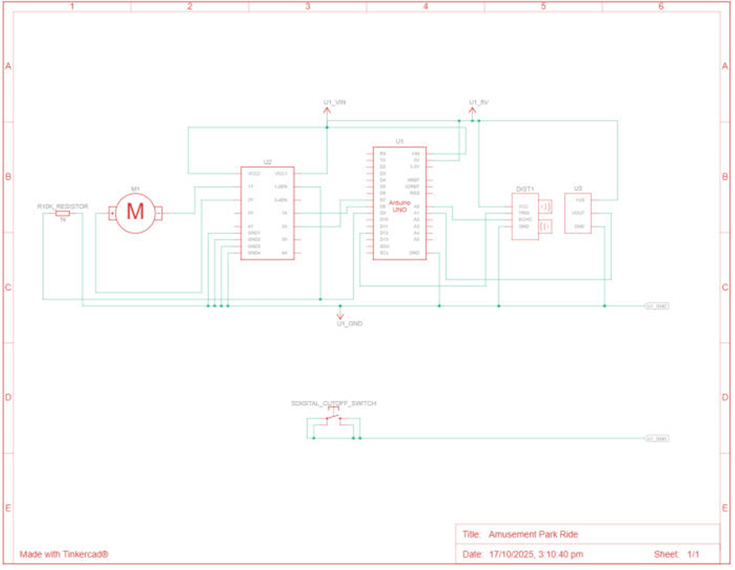
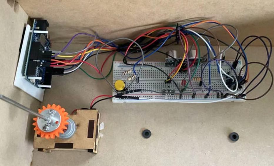
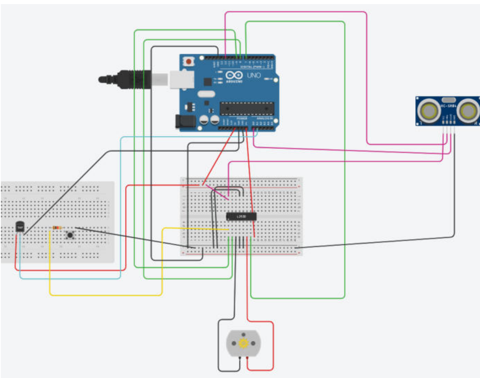
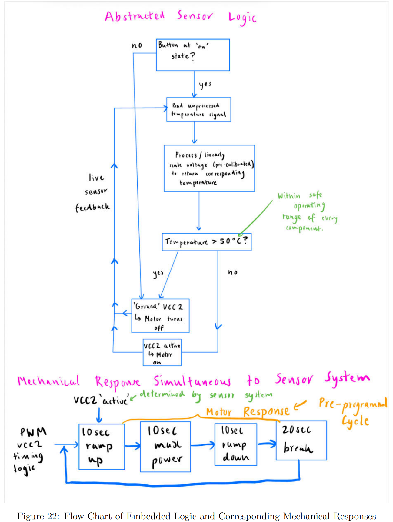
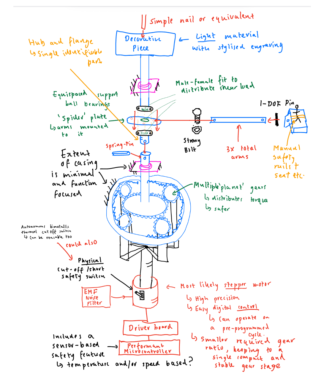
- Embedded control with hardware safety: analogue thermal cutoff plus an independent digital kill path.
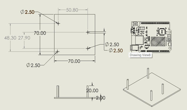
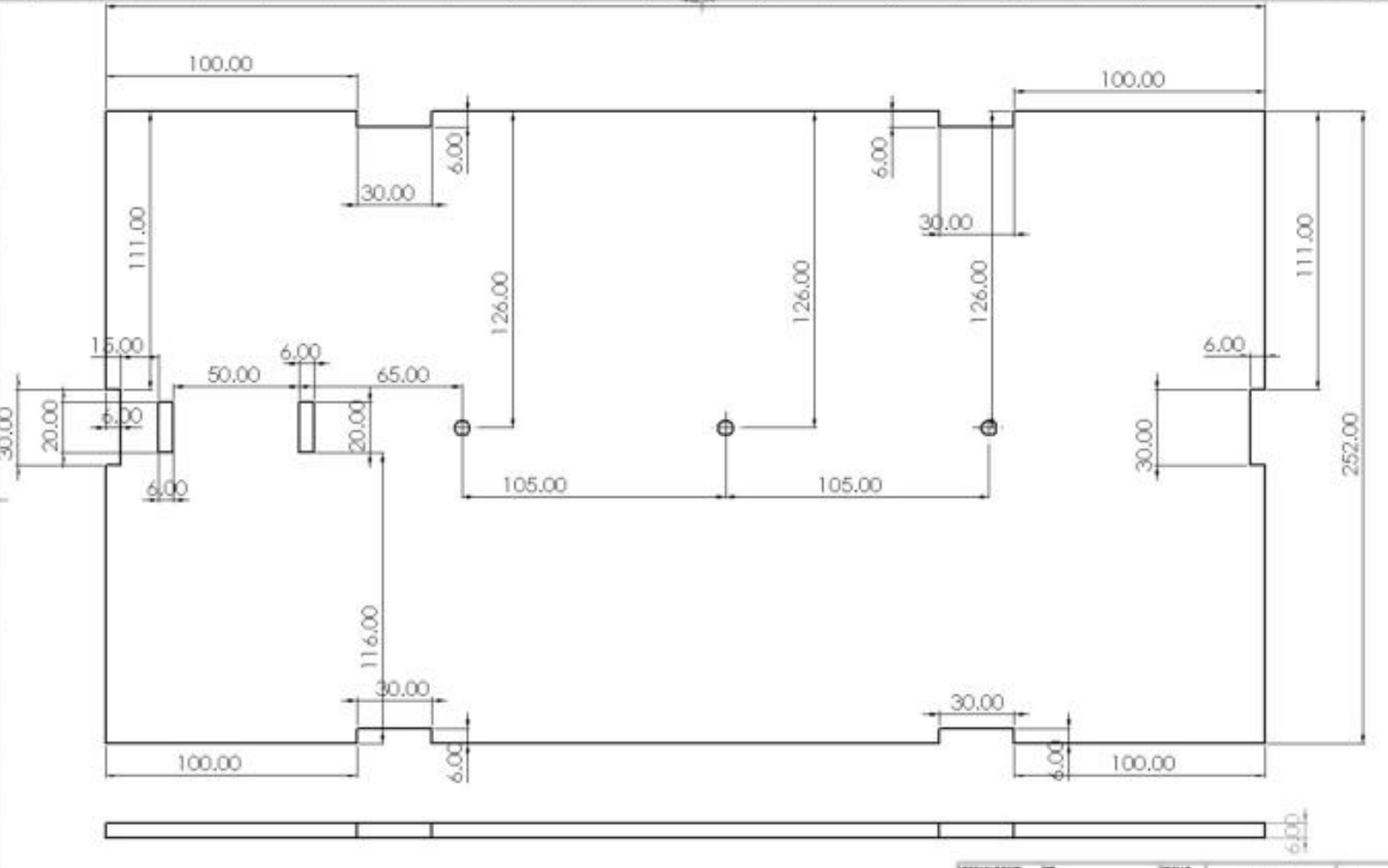
- DFM and reuse: monolithic laser-cut parts, dovetail joints, interference-fit shafts, flange/grub-screw retention.
20T pinions driving 100T/120T/120T gears across three stages, each mesh independently cleared for undercutting at 20° full depth. Early MDF teeth at module 0.8/1.0 sheared under load — module escalated to 1.5; when the first-stage pinion sheared again at the motor interface, it was re-fabricated in PLA while the remaining stages stayed MDF. Passed the five-minute continuous-durability requirement with no tooth failure or loss of shaft fit.
M260 operating point modelled on the linear torque–speed line — τ ≈ 3.2 × 10⁻⁴ N·m at 6000 rpm against a 3.5 × 10⁻³ N·m stall limit — with a 2.5 s linear ramp sized against the rotating inertia (J = 0.040 kg·m², α = 1.40 rad/s²) to keep acceleration torque clear of stall. Stepper baseline rejected after same-shaft A/B testing: perceptible cogging, higher idle draw, no functional need for angular indexing.
Bench-supply V–I sweep through the VIN–GND node into a P–V curve; identified the efficient mid-range region, confirmed 2.43 W steady-state at nominal 9 V, and tuned PWM duty to 60/255 against speed, gear wear, and driver heating.
Single control script running a 10 s ramp / 10 s steady / 10 s ramp-down / 20 s dwell cycle. H-bridge thermal throttling diagnosed under load, then closed-loop mitigated: averaged-ADC temperature sensing cuts motor supply above 50 °C, with a pushbutton kill shorting the drive as a second, fully independent path.
Spider plate and three arms re-cut as one monolithic MDF part — A/B showed less play and smoother rotation from deleting bolted-joint compliance at the arm roots. Redundant mid-height bearing blocks removed after base-and-roof constraint proved sufficient; Iglidur flanged bushings press-fit in when specified ball bearings were unavailable.